Getting Started. Power Supply
Device Operating Modes
Bootloader Modes
Logger Mode (SD Card)
Gate Mode
Player Firmware
LED Signal Values
Important: switching between the operating modes is carried out by placing jumpers in a certain position, after which it is necessary to reboot the device: to do this, turn off the power, then turn it on. The operating mode will be changed only after the reboot.
Getting Started. Power Supply
The power for the device can be supplied by Micro-USB or (in special cases) by a 12 volt power source. In the photo, the power connectors are marked as "12V Input Power". 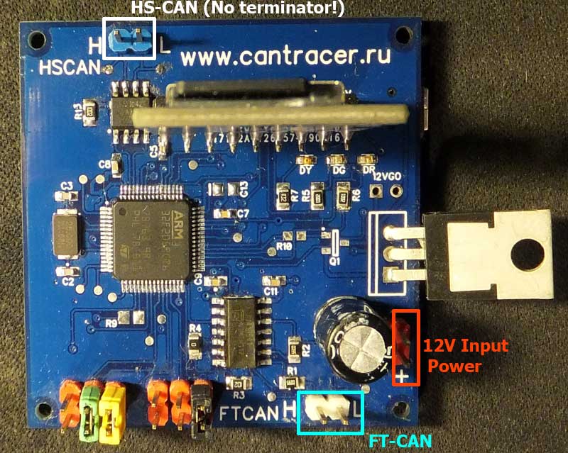
Device Operating Modes
The device can operate in the following modes:
- Bootloader mode - required to load the device firmware;
- Gateway mode - designed for device operation as FT-CAN and HS-CAN gateway;
- Logger mode - developed for collecting bus logs.
Bootloader Modes
To switch the device to the Bootloader mode, insert two jumpers into the first two slots. The photo below shows an example of installing jumpers in order to set the device to the Bootloader mode. 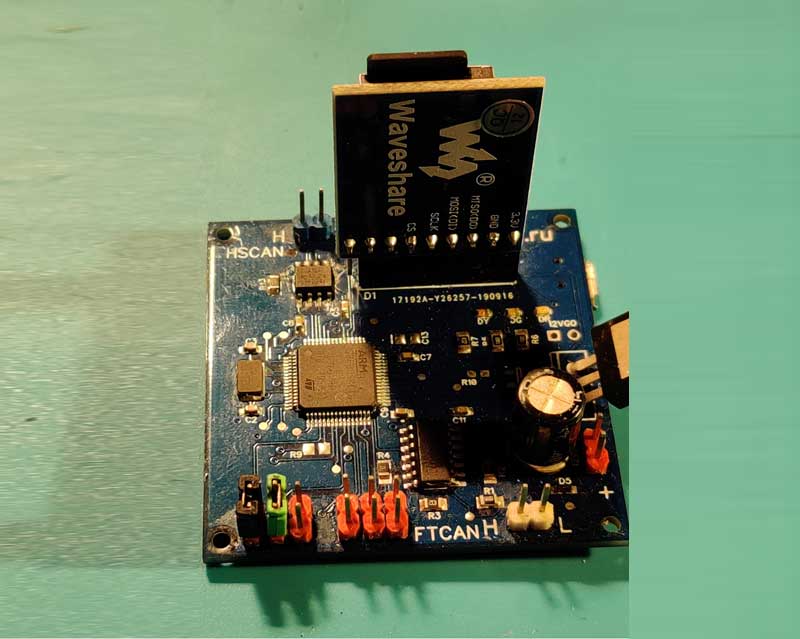
The Bootloader mode allows to install the newest Firmware update on the device. The installation of a Firmware update can be carried out in two ways:either by using the Cantracer module, or with the help of an SD-card.
Currently there are two Firmware versions available: version 50-100-125 and 50-83,3-125, which are designed to operate with different frequency assemblies. Therefore, if the last digit in the Firmware version is "7", it means that it’s a version that works with with 50-83,3-125, whereas the other Firmware versions work with 50-100-125.
In order to determine which version of the software is installed on the device or install the current version of Firmware, you can use the Cantracer module, which can be downoaded from our site and installed on PC in a regular way. The module is also available as source files and can be downloaded by selecting the Cantracer.ctp file.
The Cantracer module is designed to work with the device exclusively in the Bootloader mode.
Pressing the "ECU Information" button starts reading the ECU data: the device name, the Bootloader and Firmware versions, as well as the serial number.
The Writeflash button is intended to deploy the Firmware.bin file. To launch the file, simply select the downloaded version. Please, note that when a new version of Firmware is loaded, it should change the Firmware version number (in the Cantracer Device window).
Our device also supports stand-alone functioning , therefore Cantracer module is not required to be installed on PC for the device to work: it can be used for visualization of some processes as well as employed as a source for launching new Firmware.
Alternatively, the firmware can be launched from an SD card.
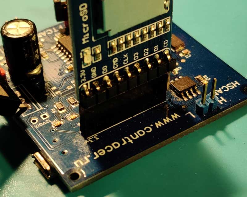
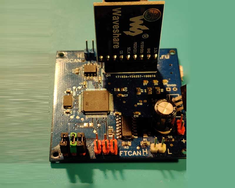
To connect SD-cards use WaveShare adapters (available at specialized trading sites: e.g. a Micro SD adapter can be purchased at AliExpress).
Please, make sure that the voltage of the adapter and the device are the same (the adapter is marked as 3.3 volts, the same voltage should marked on the device).
Note, that the SD card should be preformatted with FAT, the Firmware.bin file written to the root. This done, insert the SD card into the adapter.
On power up, if an active SD card is inserted, the indicator will produce two short yellow flashes. As soon as the device recognizes the Firmware.bin file (on boot), it will automatically install the firmware.
Logger Mode (SD Card)
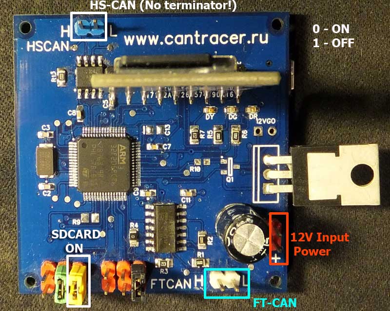
To switch the device to the Logger mode, it’s necessary to place the jumper into the position marked as "SDCARD ON" (see the photo).
Upon the reboot (that is necessary to switch the device to the Logger mode), the light will blink twice, meaning that now the SD card is active.
After rebooting and switching power supply to a mode other than Bootloader (with an SD card connected), the device will automatically start writing logs to the SD card (in case of any CAN Bus activity).
All the messages will be written in the logs (which in their turn will appear only if the frequency is set correctly, i.e. correct operating frequency should be set for both the HSCAN bus and the FTCAN bus).
Note, that in case of using an SD card, a class 10SD card is required for an uninterrupted data transfer - otherwise the data transfer speed may mismatch the reading / writing speed of the SD card.
Writing SD Card Logs
Every time the power is turned on, a file with a specific index is created on the SD card. When a new file is created, the index is incremented by one. It is recommended to regularly delete old files from the SD card, since the device creates indices as a cycle (from 0001 to 1000), so there is a risk of overwriting some necessary files.
The recorded data can be read in two ways:
1) Remove the card from the device, insert it into the card reader and read the SD card on the PC.
2) Do not remove the card from the device, just use the usb connecting cable.
In this case, the card is read only in the "BOOT"mode, which is turned on when the jumpers placed into the "FT-CAN SPEED SETTING" and "SDCARD ON" positions (see the photo).
The jumpers in the "FT-CAN SPEED SETTING" position switch on the "BOOT" mode, whereas the jumper in the "SDCARD ON" position indicates that the SD card is active.
After rebooting, the device will be detected and recognized by the computer OS as an external storage medium. Please, keep in mind that this is a USB 1.0 device, hence some data may be transfered at a lower speed.
The output logs can be sent straight to CANTracer (they have a standard CANTracer-compartible format).
If interrupted when writing data, the device will later display an error message when reading (which will still not affect the completion of the process of reading and processing data).
The logs can be saved in a text format (for further analysis).
Gate Mode
To use the Gate mode, please set the speed by placing the jumpers as required (see the photo)
For example, to set the speed up to 100 kB/s, place the "FT-CAN SPEED SETTING" jumpers into position 1-0 (see the photo).
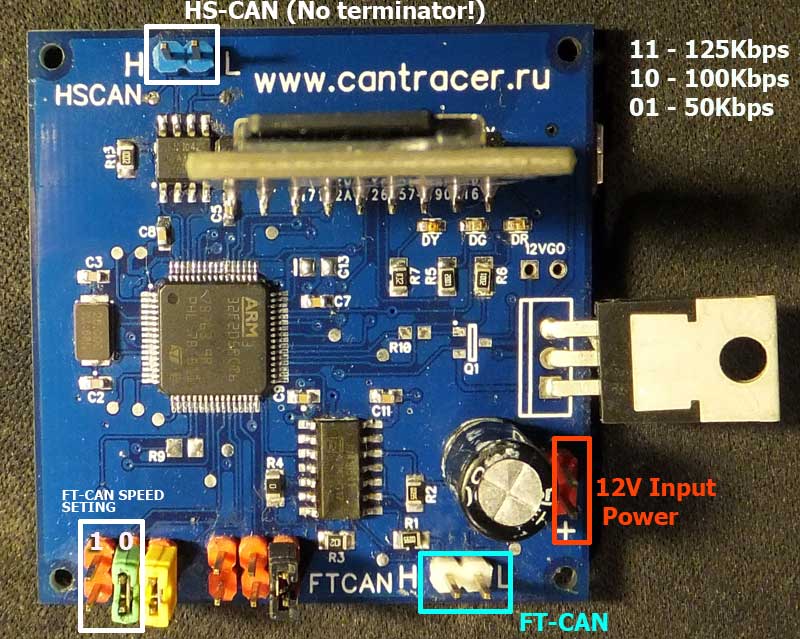
For example, to set the speed to 125 kB/s, place the "FT-CAN SPEED SETTING" jumpers into position 1-1.
In the "FT-CAN SPEED SETTING" position, the jumpers switch the FTCAN speeds.
In the "HS-SPEED" position (see the photo) the jumpers switch the HSCAN speeds (250-500-125).

Thus, by using the CanTracer, one can send various requests to FTCAN units.
If the gateway is transparent, for example, in case of Mitsubishi, you can use any other diagnostic tools. With the unit connected to FTCAN and the scanner connected to HSCAN, the scanner recognizes the unit as if it were in the car.
Player Firmware
The Player Firmware is not a device operating mode, but a separate firmware that can be downloaded from the Support section of our website.
To work with this firmware, you will need to connect an SD card adapter, since the module with which this firmware works is located on the SD card. The module should be renamed as"autorun.ctp" and placed in the root directory of the memory card. For the module syntax, see the Can Tracer Module Builder Guide. Note that the peculiarities of the application and the performance of the device processor impose their own limitations on the capacity of the module.
For example, there is no need to create different sections. There is only one section called "autorun".
[autorun]
[autorun/settings]
CANID=700
filter=000007??
mpause=400
playlog=run.trb
button="Emulate CAR"
One of the module features is the "playlog" control (still not included into CAN Tracer). It allows to send messages to the CAN bus from the file specified in the parameters. The Log is accepted only in the "trb" format, which is supported both by CAN Tracer software and the device in the logging mode. Thus, you can copy your logs from the car, send them to the card, write a short module and emulate the car in the desktop mode.
The Player mode is mainly used to simulate the presence of units in the car or on the table which is needed for analysis and diagnostics. More details on the capacities of the mode can be found in this video:
LED Signal Values
The device has LEDs that convey various information.
LED Signal Values:
• gateway enabled - three yellow blinks at start
• SD card enabled - two yellow blinks
• gateway+SD card enabled - three + two yellow blinks
• Player mode - four yellow signals
• the device is ready for operation - the green LED blinks
• a message arrived on the CAN bus - the green LED is flashing
• messages on the CAN bus arrive continuously at a high speed - the green LED is continuously on
• Message transmission from one bus to another failed - the yellow LED is on
A flashing yellow LED means an overflow of the processor's internal mail buffer; so when the CanTracer is receiving data, the buffer is not overrun and the light is not flashing.
When in the gateway mode, HSCAN and FTCAN operate in the bidirectional data transfer mode. If an error occurs during data transfer, the yellow light starts flashing.
The device also displays "fatal errors" that prevent further operation.
In such cases, the red LED turns off whereas the yellow one blinks intermittently, with short pauses.
Error Description:
| Number of blinks | Error value |
|---|---|
| 4 | sd-card error |
| 5 | CAN bus error |
| 6 | unexpected error |
| 7 | license error |
| 8 | module error |
| 9 | buffer overflow error |